Application Notes : kSA BandiT – BET Measurement Approaches
Version: 1.0
- Introduction
- Absorption Edge Wavelength
- BandiT calibration curves library
- Savitzky-Golay method
- Locating the second derivative peak
- Choosing the appropriate calibration curve
- Displaying the results in real time
- References
kSA BandiT – BET Approaches
Introduction
kSA BandiT utilizes the temperature dependence of a semiconductor’s inherent band gap to measure temperatures. With this technique, the sample either diffusely reflects or transmits light in the appropriate wavelength range. In the process, the sample can selectively absorb light with sufficient energy by transferring some of its energy to an electron in the valance band, causing it to be promoted to the conduction band. However, light that lacks the required energy can pass through the sample. The energy of the transition from absorbing to transmitting defines the optical absorption edge of the sample and is temperature dependent. kSA BandiT analyzes the spectrum of the diffusely reflected or transmitted light using a solid-state spectrometer to determine the wavelength of the absorption edge, which it converts to temperature via a set of material-specific calibration curves.
Note that this technique is fundamentally different from pyrometry, which is commonly used for temperature measurement of these materials. Pyrometry relies on the emission of blackbody radiation from a sample at elevated temperature. While kSA BandiT is also capable of measuring temperature using such blackbody-radiation-based approaches, the absorption edge technique can offer considerable advantages. For example, unlike pyrometry, it can be utilized at very low temperatures. Furthermore, this technique does not rely strictly on an intensity-based measurement; therefore, it is insensitive to many factors that ultimately limit the performance of pyrometry. These factors include viewport coatings, changes in the sample’s emissivity, and stray light from hot sources.
Determining the Absorption Edge Wavelength
The first step in measuring the sample temperature via this technique is to determine the absorption edge wavelength. This can be achieved using either transmission or reflection spectra. For materials such as GaAs, InP, and Si, which have room-temperature band gaps in the 1-1.5 eV range, the absorption edge lies in the near infrared (NIR) portion of the spectrum. For materials that have wider band gaps, such as CdTe, CdZnTe, GaN, and SiC, the absorption edge lies in the visible/near-UV portion of the spectrum.
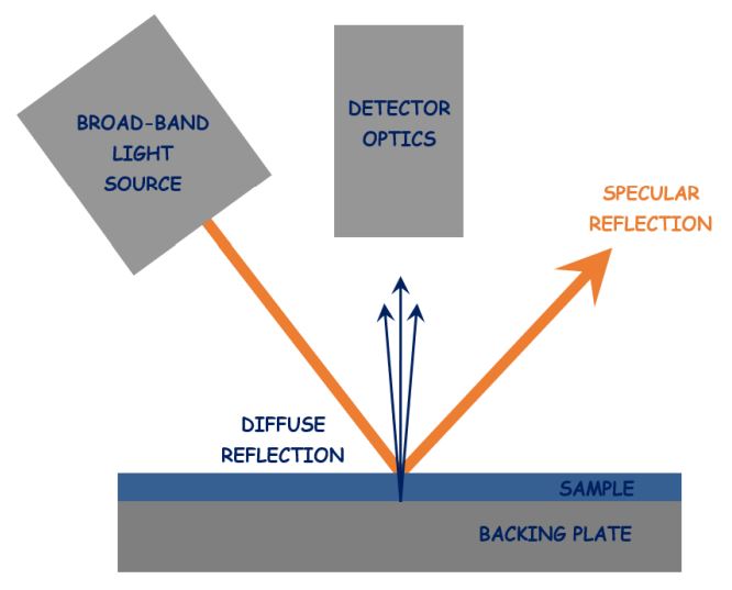
Figure 1 illustrates the BandiT configuration in reflection mode. In this mode, light from a broadband source passes through the sample and scatters off the backside and/or any backing plate. It then passes back through the sample and is selectively absorbed in the process.
Note that the amount of light absorbed is greater in reflection mode compared to transmission mode because the light must pass through the sample twice. Also note that the specular (i.e., first surface) reflection should be avoided, as it does not contain the necessary absorption signal and serves only to obscure the diffusely reflected signal (which is considerably less intense). For this reason, it is best to have at least 10 degrees of separation between the detector and the specular reflection of the light source. Furthermore, in reflection mode, a single-side-polished sample (SSP) gives dramatically more signal than a double-side-polished (DSP) sample, as the polished backside produces relatively little diffusely reflected light. In the case of the latter, a backing plate (typically Mo or PBN) usually has sufficient texture to provide the required intensity of diffusely reflected light.
To determine the absorption edge wavelength, one must perform multiple steps: smooth the raw spectrum, subtract the background, normalize the resulting spectrum, find the inflection point, and finally, perform a linear fit.
1. Smooth the raw spectrum
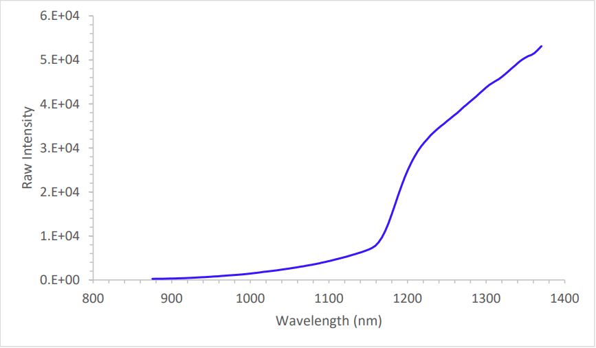
kSA BandiT first smoothes the raw spectrum (Figure 2) using a simple boxcar (i.e., moving average) method, followed by an optional clipping to remove the ends of the spectrum that may contain stray light from the substrate heater or other sources of noise. Note that the application ignores any spectra with peak intensity outside either the floor or ceiling cutoff values.
 Figure 2: Raw BandiT spectrum of GaAs at room temperature
3. Normalize the spectrum, find the inflection point, and perform a linear fit
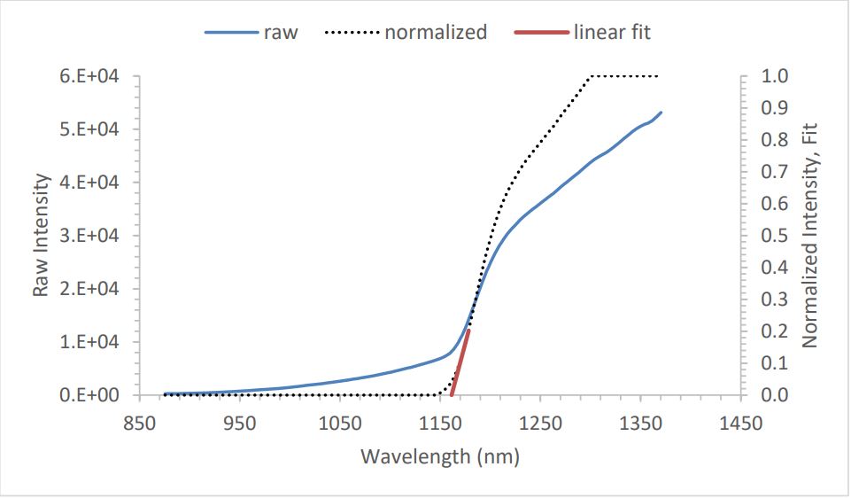
kSA BandiT normalizes the spectrum so that the maximum value is 1. The next step is to find the inflection point, i.e., the steepest point of the curve, by calculating the first derivative and searching for the peak. The application uses point-by-point differentiation, followed by more boxcar smoothing (refer to the settings in Figure 4).
 Figure 4: Band edge settings: linear fit approach
At the inflection point, the curvature changes direction from concave upwards to concave downwards. In other words, the second derivative changes sign from positive to negative, passing through 0 at this point. kSA BandiT then determines the absorption edge wavelength from the intersection of a linear least-squares fit to a portion of the absorption edge below the inflection point (the red line in Figure 5) with the baseline. For more details on this process, refer to the kSA BandiT User Manual.
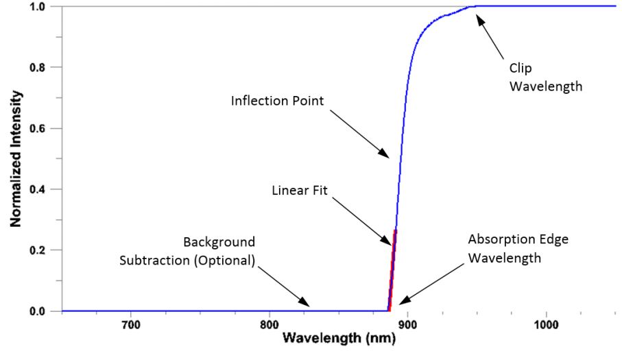 Figure 5: Normalized BandiT spectrum of GaAs at room temperature
kSA BandiT Calibration Curves Library
kSA BandiT includes a library of empirically determined calibration curves that map the absorption edge wavelength to temperature. These curves are generated by attaching a Type C thermocouple to a sample, and slowly ramping the temperature using a standard radiative-heating substrate stage in a UHV chamber in the k-Space lab. If needed, the TC readings are corrected by comparing them to blackbody measurements taken at the maximum temperature. The blackbody measurements are in turn calibrated using a commercial blackbody source. Note that the primary factors that affect the calibration curve are material type, doping, and thickness. For most semiconductor materials, the band gap narrows (i.e., the absorption edge wavelength increases) with increasing temperature. Figure 6 shows a typical calibration curve for semi-insulating GaAs.
 Figure 6: S-I GaAs calibration curve
The approach described above (which uses a linear fit to the portion of the absorption edge below the inflection point) performs well under most circumstances. However, it tends to break down when there is a large background. This occurs at high temperatures due to the emission of large amounts of blackbody radiation from the sample, or if the material is highly doped. These effects tend to obscure the location of the true absorption edge, as shown in Figure 7, which represents a linear fit to the GaAs absorption edge at high temperature.
Savitzky-Golay Method
The ill effects discussed above can be mitigated by determining the absorption edge wavelength using the “knee” in the spectrum, which is the point with the greatest upward curvature (i.e., where the second derivative is at its maximum). The determination of the knee wavelength is facilitated by the recent implementation of a digital smoothing filter in kSA BandiT that uses the Savitzky-Golay (S-G) method. This method was developed to significantly reduce the amount of noise in spectral data, while retaining the shape of the original peaks, resulting in minimal loss of resolution (Savitzky & Golay, 1964; Schafer, 2011). It is more sophisticated than the simple boxcar method that is typically used. The essence of this approach is low-pass filtering via a local least-squares polynomial approximation. Note that symmetric Savitzky-Golay filters (i.e., those with equal widths to the left and right of the point in question) have zero phase, so that spectral features do not experience any shifting. As Figure 8 shows, the filter can be extremely successful at smoothing a very noisy signal. As an added feature, because it uses a polynomial smoothing function, it is trivial to also obtain the derivatives of various orders (up to the order of the polynomial used).
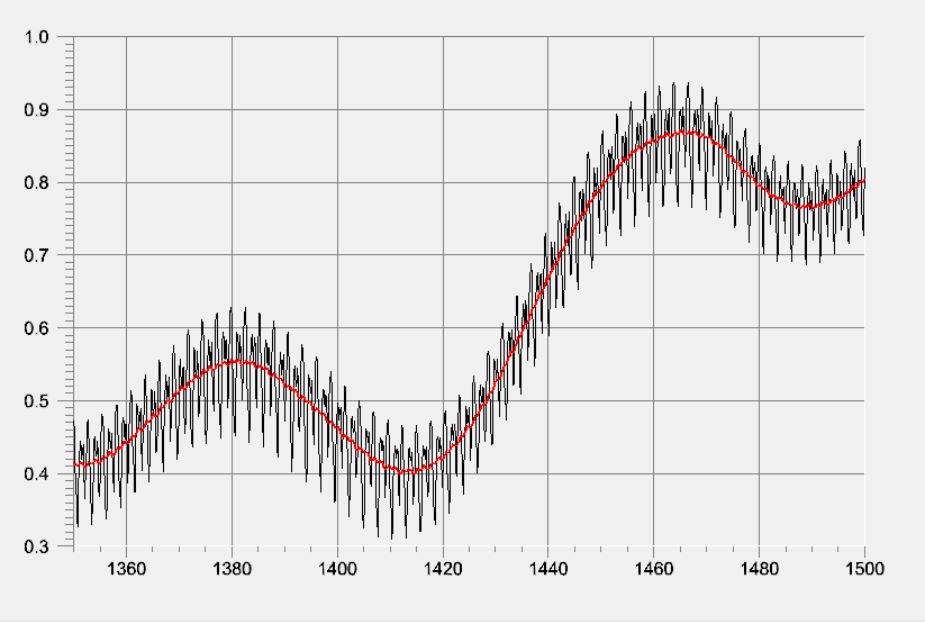 Figure 8: Smoothing of a noisy signal using the Savitzky-Golay method
In this S-G second derivative approach, the kSA BandiT software first smoothes the raw spectrum using the Savitzky-Golay method (note that the Raw Spectra Boxcar value should be set to 1 to disable the conventional boxcar smoothing of the raw spectrum – refer to the settings in Figure 9). If the Normalize datapoint setting is enabled, the application will normalize the smoothed spectrum so that the maximum value is 1. This enables the other intensity-dependent settings to have a consistent reference value.
Enter the total width of the symmetric Savitzky-Golay smoothing window in the Boxcar field on the Band Edge Calculation tab. (Note that this value must be an odd number.) For example, if the value is N, each data point will be smoothed using the (N-1)/2 neighboring data points on either side. The larger the width, the greater the amount of smoothing. Finally, enter the Order, which represents the order of the smoothing polynomial (typically 2).
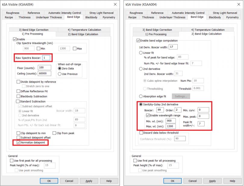 Figure 9: Band edge settings: Savitzky-Golay second derivative approach
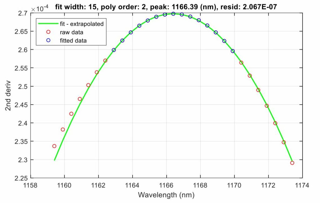
To determine the absorption edge wavelength, the application finds the peak in the second derivative, subject to several filters. If you check the Enable wavelength range box, the application will reject any peak lying outside the specified wavelength range. In addition, it will reject any peak that has a value less than the value in the Min curv field or greater than the value in the Max peak field. Finally, the application determines the precise peak location by performing a quadratic fit to the 2N+1 points centered on the selected peak (see Figure 12). The choice of this fitting width will be discussed in more detail in the following section.
Figure 10 and Figure 11 illustrate the absorption edge wavelength determined in this manner for GaAs at room temperature and at high temperature, respectively. Note the large amount of blackbody radiation at high temperature. Also note the broadening of the peak in the second derivative. Nonetheless, the “knee” can be found quite precisely and repeatably.
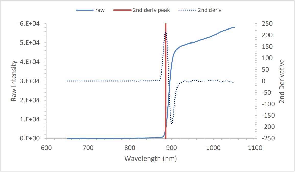 Figure 10: Room-T GaAs – raw spectrum and second derivative
 Figure 11: 625°C GaAs – raw spectrum and second derivative
Locating the second derivative peak
As discussed previously, kSA BandiT determines the precise location of the second derivative peak by performing a quadratic fit to the 2N+1 points centered on the selected peak. For example, the range typically used for GaAs is the central point ± 7 points (see Figure 12).
Choosing the appropriate calibration curve
Note that the absorption edge wavelengths determined using the linear fit and S-G second derivative approaches are slightly different from each other, as shown in Figure 13.
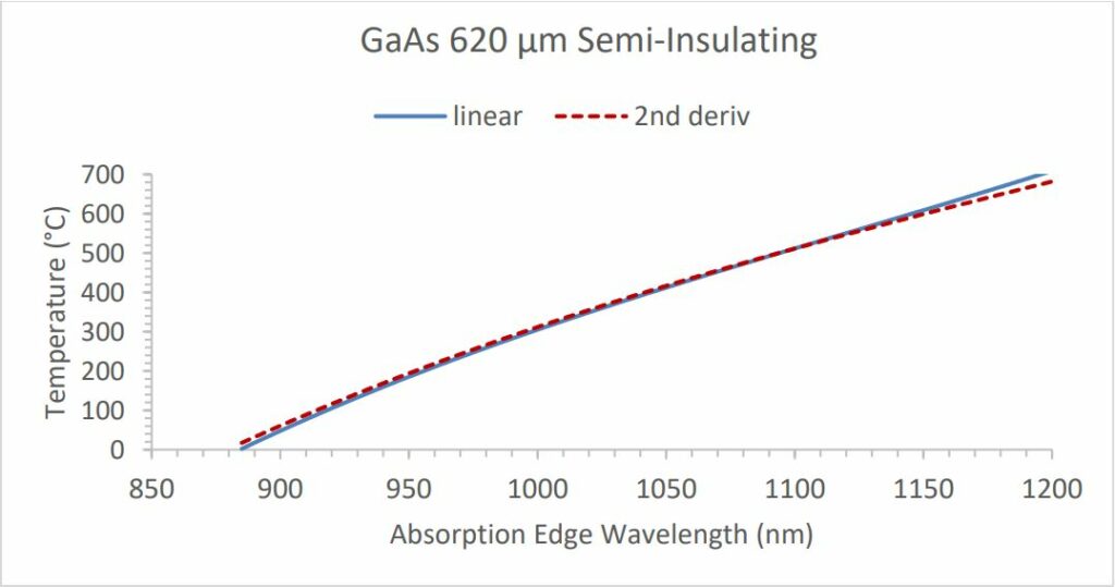 Figure 13: S-I GaAs calibration curve comparison
Therefore, to obtain the best accuracy when using the S-G approach, use only calibration curves that were specifically created for this application. These have the designation “S-G 2nd Deriv.” in the Comments column (see Figure 14).
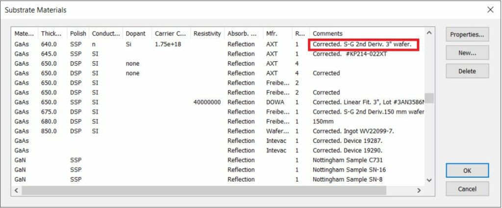 Figure 14: Substrate materials library
Indirect band gap materials like Si are more difficult to measure because the second derivative peak is much broader, and therefore requires a wider fitting range (see Figure 15 and Figure 16). You can typically obtain good results by increasing the width to ± 50 points (see Figure 17). Note that at temperatures above 500°C, the Si spectrum becomes so broad that it is difficult to discern the absorption edge. Depending on the dopant type and concentration, this represents a rough upper limit for band edge-based temperature measurements. However, you can extend this limit by using the strobed stray light removal technique. In this technique, the system captures spectra with the light source alternately turned off and on. By subtracting the light-off spectrum from the light-on spectrum, the effects of the blackbody radiation can be greatly reduced. This allows band edge-based temperature measurements to be extended to higher temperatures. For more details, refer to the kSA BandiT User Manual.
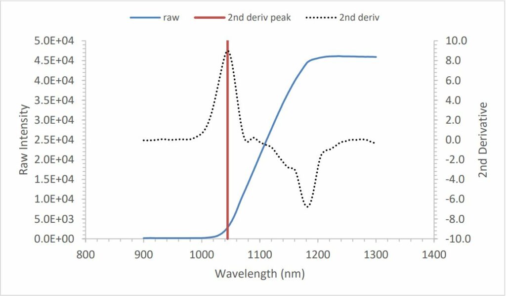 Figure 15: Room-T Si – raw spectrum and second derivative
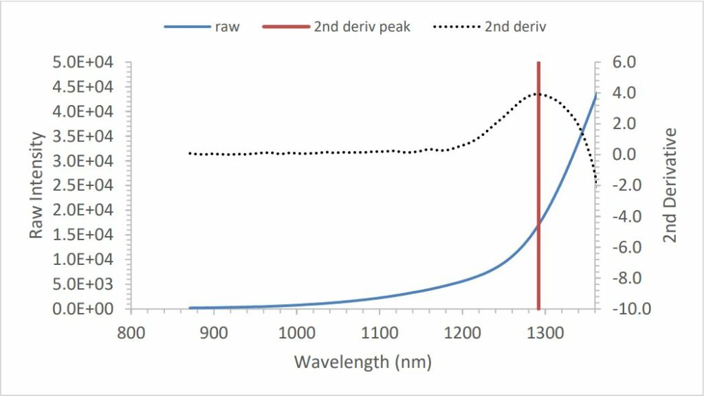 Figure 16: 500°C Si – raw spectrum and second derivative
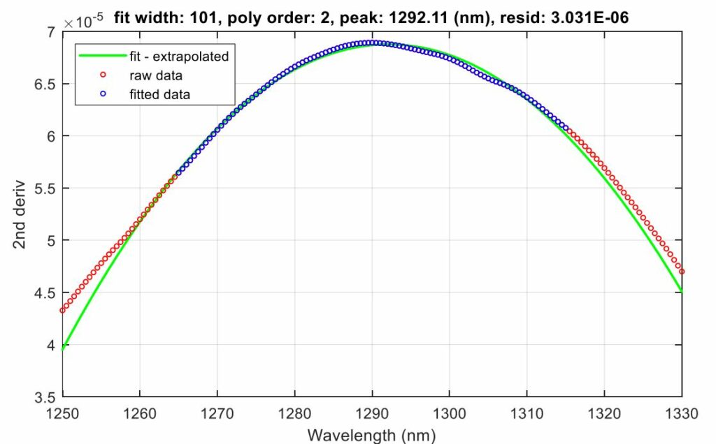 Figure 17: Second derivative peak fitting – 500°C Si
Displaying the results in real time
During data acquisition, you can display the second derivative in real time as follows.
- In the kSA BandiT software, select the View > Real-time BandiT Spectra.
- As shown in Figure 18, right-click on the chart, select Properties, and then click the Data Filters tab.
- From the drop-down list in the first row, select Normalizer.
- In the second row, select Savitzky-Golay.
- Click the corresponding Properties button and enter values in the Derivative number, Boxcar Width, and Smooth Order fields to match the recipe settings.
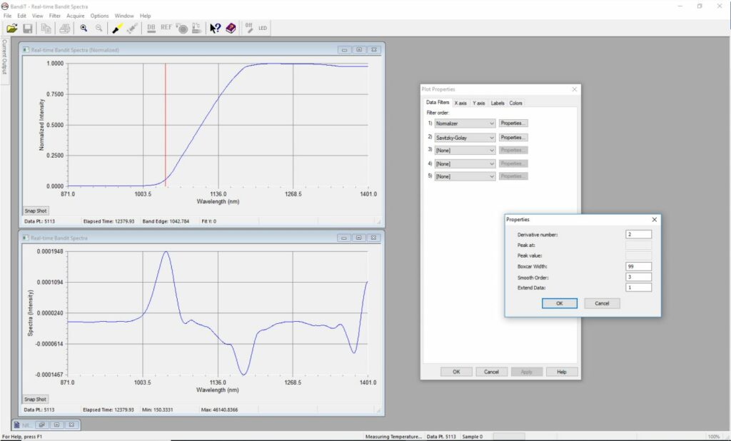 Figure 18: Real-time chart displaying the second derivative
References
Savitzky, A., & Golay, M. (1964). Smoothing and Differentiation of Data by Simplified Least Squares Procedures. Analytical Chemistry, 36, 1627-1639.
Schafer, R. W. (2011, July). What Is a Savitzky-Golay Filter? IEEE Signal Processing Magazine, pp. 111-117.


