Application Notes : kSA BandiT– Growth Rate Analysis
Version: 1.0
- Growth Rate Analysis with kSA BandiT
- Collecting and Analyzing Spectra
- Growth Rate Calculation and Cross Calibration
Growth Rate Analysis with kSA BandiT
Pyrometric Interferometry
- Integrated with kSA BandiT temperature monitor
- R&D and production MBE/MOCVD compatible
- Post-growth analysis with layer structure ‘fingerprinting’
- In-situ growth rate calibration avoids offline processing
- User-selectable pyrometry wavelengths ensures match to today’s materials
- Select pyrometer wavelength based upon layer material band gap
- Use with existing kSA BandiT hardware
- Fully supported though new integrated kSA BandiT Help Manual
Introduction & Motivation
The kSA BandiT system now has the ability to determine deposition rate from pyrometric interference oscillations in radiated light from the sample surface. These oscillations occur when a film is being deposited with a different index of refraction from the under layer or substrate. Specifically, when the sample is hot enough to emit blackbody radiation, this radiation is emitted in all directions. Radiation that is emitted back into the sample is reflected off the interface between the film and the substrate. This reflected radiation then interferes with radiation that is emitted forward from the surface. BandiT collects the intensity oscillations in the radiation across the whole range of wavelengths. The growth rate is extracted by fitting these oscillations using simple optics equations. The only requirements for this type of analysis with the BandiT system are: 1) a film and substrate of different material composition; 2) a semitransparent film and substrate (satisfied by most semiconductor materials). 3) a sufficiently thick film, about 2000 Å or greater.
In this paper we describe how kSA BandiT acquires data for growth rate analysis, as well as how to perform the analysis within the kSA BandiT software.
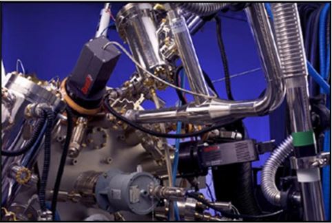
kSA BandiT two port design installed onto Veeco GENIII MBE System. Single port versions available for other MOCVD and MBE systems
Collecting and Analyzing Spectra
kSA BandiT collects wavelength resolved light intensity in the range from 870-1400nm (NIR unit) or 380-1100nm (VIS unit). Spectra in these ranges are typical for monitoring the band-edge based temperature of GaAs, Si, InP (NIR unit) and GaN, SiC, ZnO (VIS unit). In addition to storing data in the typical temperature monitoring format, BandiT also gives you the ability to store data in a “Pyrometric Scan Image” (Figure 1). In this format, each acquired spectra is stacked below the previously acquired spectra, thereby generating an image of stacked spectra, where the time evolution of the image is from the top to the bottom of the image.
Looking at Figure 1 from left-to-right, it is easy to see the absorption edge of the substrate material as the transition from dark (where absorption occurs) to light (where the sample is transparent and oscillations are easy to see). Together with stacking, this gives the Pyrometric Scan Image the time-dependence of the light intensity at each wavelength within the range of the spectrometer. As a result, performing a vertical line profile of the above image at a given wavelength gives an intensity plot like that shown in Figure 2. Here, the selected wavelength is 1228nm. Note that moving the line scan across the image (while leaving in the vertical orientation) shows the data at different wavelengths. Seen more clearly in Figure 2, the data in both figures is of the initial deposition of GaAs followed by a growth interrupt, and then deposition of AlGaAs.
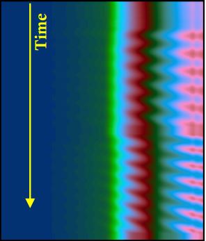 Figure 1: Scan image of GaAs/AlGaAs pyrometric oscillations.
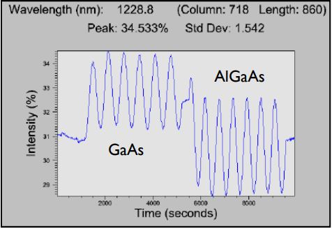 Figure 2: Pyrometric interference oscillations at 1228nm for GaAs/AlGaAs deposition.
Growth Rate Calculation and Cross Calibration
Having captured the intensity oscillations of a particular growth run, one can determine growth rate by analyzing an individual process. That analysis is done with simple optics equations, utilizing the fact that the emitted radiation reflects off the interface between the film and substrate and interferes with radiation emitted directly from the surface. So, a peak in intensity occurs whenever the optical path length of the film is a multiple of the wavelength of light. That is, a peak in intensity occurs at thickness intervals of λ/2η, where η is the index of refraction of the film. It follows that the oscillation period will be:
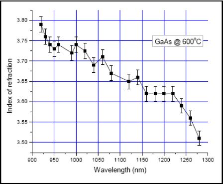 Figure 3: GaAs dispersion curve determined using RHEED oscillation growth rate data and pyrometric interference oscillation data.
![\[ T = (I/G)*(\lambda/2\eta) \]](https://k-space.com/wp-content/ql-cache/quicklatex.com-898cb28901468c00fd1397b969304b68_l3.png "Rendered by QuickLaTeX.com")
where G is the film deposition rate. The period, T, is determined by frequency analysis of the acquired data set. The growth rate is simply:

In both versions of the equation, the unknown is the index of refraction, η, which depends on wavelength and also changes at the elevated temperatures typical of III-V film deposition. To determine η, one can simultaneously gather pyrometric interference data (T) from kSA BandiT and growth rate data (G) from an independent source, such as RHEED oscillation data. With known T and G, simply solve the above equation for η. Solving for η at every wavelength gives a material-temperature dependent dispersion curve. For example, Figure 3 shows such a dispersion curve for η for GaAs at 600°C in the wavelength range 900-1280nm.
After zooming in on an individual process, such as shown in Figure 4, one can determine that layer’s growth rate by using BandiT’s Pyrometric Growth Rate analysis. This analysis performs a frequency analysis on the oscillations and extracts the resultant deposition rate using the equation above. Figure 5 shows the final output, displaying frequency (both peak and weighted) found via Fourier transform power spectrum, calculated growth rate (G), and inputted index of refraction (η). This technique gives absolute growth rate, typically accurate to within 1%.
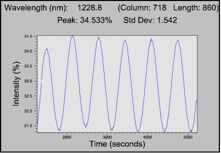 Figure 4: Subset of Figure 2 data, allowing growth rate analysis of the GaAs deposition layer.
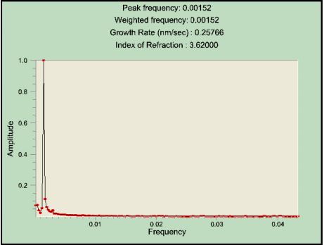 Figure 5: BandiT growth rate analysis window.
Growth Rate: A Powerful Addition to the kSA BandiT Temperature Monitor
The data presented here shows that the kSA BandiT system has the sensitivity and analysis capabilities to perform growth rate and thickness analysis using selectable wavelength pyrometric interferometry for in-situ calibration of growth rate during MBE and MOCVD growth. This capability, combined with kSA BandiT’s direct band edge and selectable wavelength pyrometry temperature measurement capability, make it a powerful in-situ monitoring and diagnostic tool for today’s semiconductor materials. Please contact k-Space Associates for more details.