Product Specifications : kSA ICE
Version: 1.0
- kSA ICE
- kSA ICE Modules and Real-time Analysis Capabilities
- kSA ICE Optical Components and Modular Enclosure
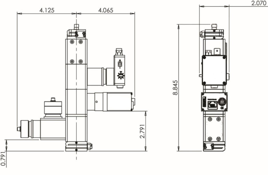
- Typical kSA ICE Optical Head Design
- kSA ICE System Hardware Specification
- MOCVD Reactor Requirements
- kSA ICE Integrated Software
- Distributors
kSA ICE - Integrated Control for Epitaxy
Real-time Integrated
Metrology for MOCVD
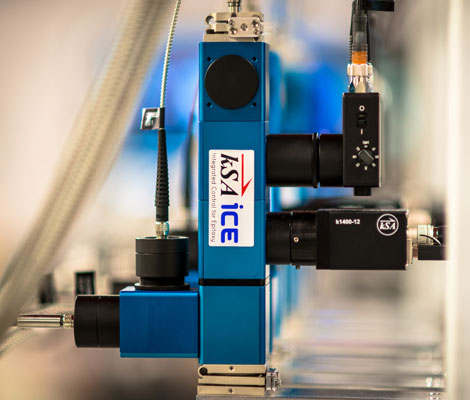
The k-Space Integrated Control for Epitaxy system (kSA ICE) is a modular in-situ metrology tool designed for today’s MOCVD reactors. It integrates various kSA measurement technologies into a single optical head that is capable of measuring:
- Reflectivity
- Growth Rate
- Film Thickness
- Temperature
- Wafer Curvature
- Film Stress
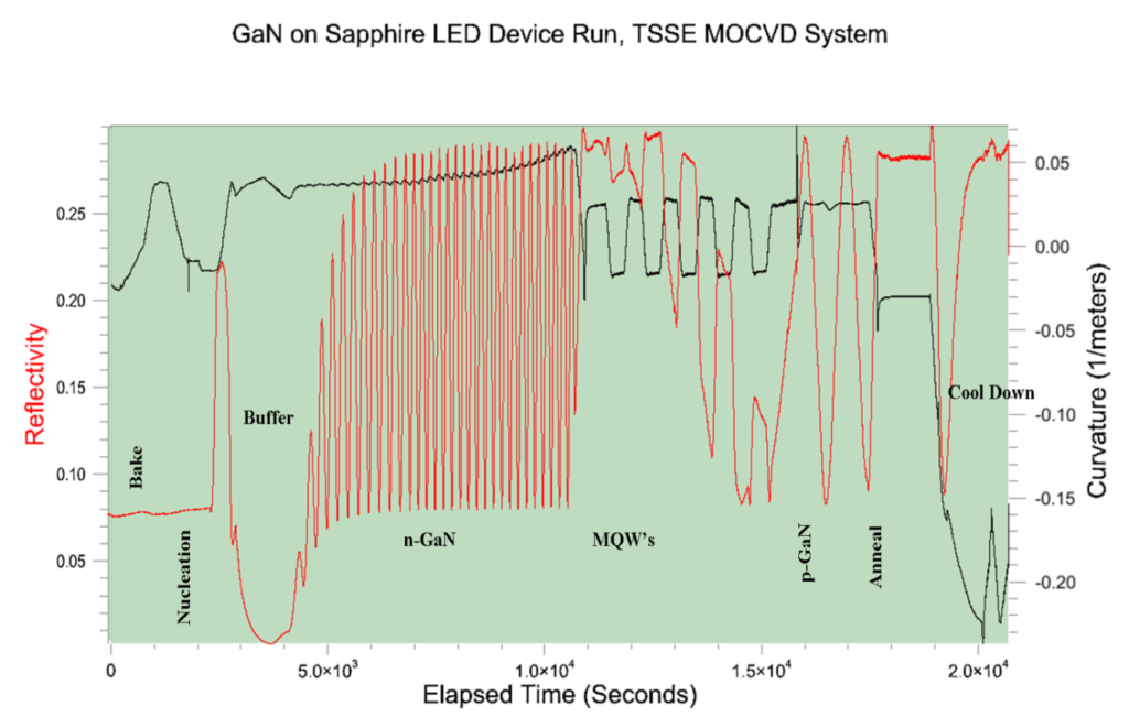
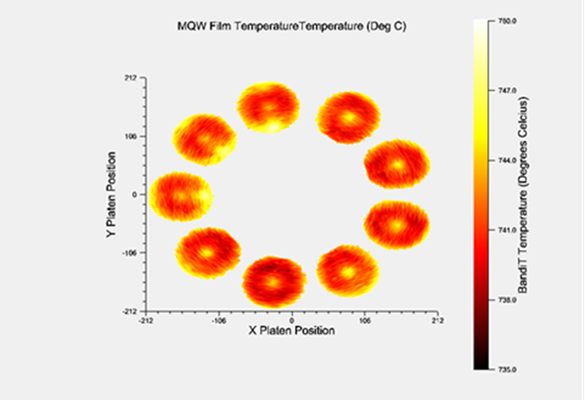
in real-time during MOCVD growth, annealing, and etching. Each measurement capability is modular and the tool can be configured based on the customer’s requirements. The reflectivity module (-R) uses a laser in combination with a high speed photo detector to monitor and fit the surface reflectivity, yielding real-time film thickness, growth rate, and optical constants (n, k). The curvature module (-MOS) monitors the substrate curvature with an array of parallel laser beams, detecting stress-induced changes via relative laser spot spacing on a high resolution camera. The emissivity corrected pyrometry module (-ECPR) provides measurement of the wafer/wafer pocket temperature, while compensating for wafer emissivity changes. The -ECPR module also offers a 960 nm LED reflectivity measurement and subsequent growth rate determination at this wavelength. Add-ons to an ICE tool include LED-based reflectivity modules at additional wavelengths and band edge thermometry (-BE) for the absolute semiconductor temperature measurements such as for GaN on GaN, Sapphire, or SiC substrates. As an accessory to -ECPR, the ICE SpectraTemp calibrator (ICE-SPECT) provides insitu temperature calibration using blackbody emission curve fitting via collection of spectra in the range of 870-1670nm. This full suite of technologies integrated into the kSA ICE system provides the most powerful and comprehensive in-situ metrology tool in the market.
kSA ICE Modules and Real-time Analysis Capabilities
| kSA ICE | -R | -ECPR | -MOS | -BE |
|---|---|---|---|---|
| Reflectivity/Growth Rate | Emissivity Corrected Pyrometry and Reflectivity | Curvature | Band Edge |
| Module Capabilities | Description | ||||
|---|---|---|---|---|---|
| Reflectivity, Film Thickness, and Growth Rate (-R) |
|
||||
| Emissivity Corrected Pyrometry and Reflectivity (-ECPR) |
|
||||
| Wafer Curvature and Stress (-MOS) |
|
||||
| Semiconductor Band-Edge Temperature, Growth Rate, and Surface Roughness (-BE) |
|
||||
Please note that most specifications are materials and reactor-dependent.
1 Film thickness and growth rate accuracy is film thickness dependent. Generally, this accuracy is achieved after the film thickness reaches ~ ¾ λ divided by the index of refraction of the material being deposited, e.g. a GaN (n = 2.3) deposition growth rate accuracy of ± 1% using 660 nm light is achieved after a ~ 210 nm of a single epilayer is deposited.
2 Resolution measured by one standard deviation of the measured temperature. Temperature range is configurable based on specific requirements; e.g., 550°C-1300°C for AlN growth. Temperature resolution is ± 0.2 °C for temperatures above 600°C.
3 Curvature specifications are reactor dependent; the above specifications are based on a typical setup with detector to sample distance of ~ 0.3 m. A smaller convex radius of curvature minimum value, -0.17 m, is achieved with an optional large format detector.
4 Temperature range is material/structure dependent, e.g., 300 -1200˚C for GaN and SiC templates/substrates. Thickness measurement requires at least 1.2 µm of film (GaN on sapphire), but can then be used to monitor very small (~ 1 nm) incremental changes. For other materials and structures, please contact k-Space for the appropriate -BE specifications.
kSA ICE Optical Components and Modular Enclosure
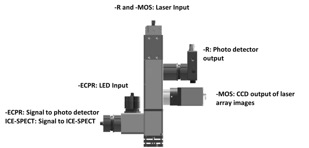
kSA ICE uses customized optics for maximizing each signal for the highest performance required for the specific measurement and wavelength range. The curvature module (-MOS) utilizes a wavelength-tuned etalon to generate an array of parallel laser beams from a single diode laser source. The reflectivity module (-R) uses a high efficiency beam splitter and collimating optics to ensure high speed and high S/N reflectance signal, while the temperature modules (-ECPR, or -BE) use hot and cold mirror optics to ensure that signals are optimized in specific wavelength ranges, while having no impact on the other measurements. If the -BE option is requested, an additional module is added to the kSA ICE optics head. This module includes a broadband light source, which then requires a slightly larger viewport geometry (compared with the standard kSA ICE system) for taking diffuse reflectance measurements. All optics are rigidly mounted to reduce vibrational noise. All components are stabilized and/or temperature controlled to maximize lifetime and signal stability during measurements.
Typical kSA ICE Optical Head Design
kSA ICE System Hardware Specification
Base system configuration:
kSA ICE systems are configured based on the technology components selected by the end user. For example, an ICEECPR system provides a kSA ICE tool configured only for measurement of 960 nm ECP Temperature and Reflectivity. The table below outlines the hardware configuration for each module (-MOS, -R, -ECPR, and -BE).
| -MOS | -R | -ECPR | -BE | |
|---|---|---|---|---|
| Spot Diameter or Collection Area on Wafer | 1 x 2 laser spot array, ~0.8 mm spot diameter, ~ 4 mm spot spacing | 1 x 2 laser spot array, ~0.8 mm spot diameter, ~ 4 mm spot spacing | ~3 mm spot diameter | ~8 mm2 collection area |
| Calibration Type | kSA-supplied calibration mirror(s) or wafer | Known reflectivity wafer (i.e., sapphire, silicon) | With external ICE-SPECT module (based on blackbody curve fitting) | Based on substrate calibration file |
| Cable Length and Type from optical head to racks | 10 m CAT5 | 10 m fiber optic 30 ft power/data cable | 10 m fiber optics (QTY 2) | 10 m fiber optic (QTY 2) |
| Light Source | Laser Wavelength: 660 nm nominal Laser Output Power: ~0.5 mW exiting optical head Stability: ≤ 0.2% | 960 nm HBLED | BE-600: 300 W Xenon light source BE-1400 and -BE-1670: Tungsten Halogen light source |
|
| Sensor | 2/3” format camera, 1360x1024 pixels, 6.45 μm cell size | Amplified silicon photo detector | Amplified silicon photo detector with 960nm 10nm band pass filter | BE-600: 350-600 nm spectrometer BE-1400: 870-1400 nm spectrometer BE-1670: 870-1670 nm spectrometer |
| Acquisition Time | 10 µs to 2 ms | 0.2 ms, typical | 0.2 ms to 1ms, typical | ~1 ms typical |
| Data Acquisition* | 5 - 25 Hz typical | 5 - 25 Hz typical | 5 - 25 Hz typical | 5 - 25 Hz typical |
| Communications and I/O Interface | TCP/IP Interface and optional analog/digital I/O |
|||
| Control Unit | 19” 4U rack CPU/controller WindowsTM 10 Professional 64-bit, QuadCore Processor, 8GB DDR3 SDRAM, 500GB (minimum) SATA Hard Disk, 512MB DVI+HDMI Video Card, Gigabit Ethernet, USB2, USB3, DVD +/-RW, USB keyboard, USB optical mouse, 22” flat panel monitor. Includes microcontroller for proper triggering/synchronization to rotation and angle-specific data acquisition triggering. Controller specifications are subject to change at any time. |
|||
* Reactor rotation speed dependent. For one measurement per rotation at 1500 RPM the frequency is 25 Hz.
Controller hardware rack configuration:
The kSA ICE hardware configuration for a typical kSA ICE system requires a single CPU/hardware rack (standard 4U height) and a source rack for LEDS and/or lasers (standard 2U height). Additional 2U and/or 3U hardware racks may be required for additional ICE optical heads such as for synchronous multi-zone control.
Additional upgrade or add-on options:
Optional add-ons and upgrades are also available to accommodate other applications and materials or to further enhance the functionality of the tool, as needed by the end user. If a particular upgrade or customization is required and is not listed below, please contact k-Space for more information.
| Options | Description |
|---|---|
| 405 nm Reflectivity for -ECPR ICE-405LEDR/U |
|
| 532 nm Reflectivity for -ECPR ICE-532LEDR/U |
|
| 660 nm Reflectivity for -ECPR ICE-660LEDR/U |
|
| Large Format/High Resolution camera for -MOS ICE-HRD/U |
|
| SpectraTemp Calibrator for -ECPR3 ICE-SPECT |
|
| Wafer Mapping ICE-MWSD/U |
|
| Additional ICE Optical Heads |
|
Please note that most specifications are materials and reactor-dependent.
1 Film thickness and growth rate accuracy is film thickness dependent. Generally, this accuracy is achieved after the film thickness reaches ~ ¾ λ divided by the index of refraction of the material being deposited, e.g. a GaN (n = 2.3) deposition growth rate accuracy of ± 1% using 405 nm light is achieved after a ~ 132 nm of a single epilayer is deposited.
2 Curvature specifications are reactor dependent; the above specifications are based on a typical setup with detector to sample distance of ~ 0.3 m.
3 As an accessory to an ICE-ECPR tool, ICE-SPECT connects to the same fiber as a -ECPR module when used for in-situ -ECPR calibration. It also uses the kSA ICE software and license key provided with the kSA ICE system for operation.
MOCVD Reactor Requirements
The kSA ICE system mounting configuration varies based on the particular MOCVD reactor for which it is configured. Standard viewport sizes include 1.33” o.d. (mini-conflat) and larger and slit-style viewports (for Veeco k465i and Aixtron G-series reactors). k-Space can manufacture and supply custom mounts and x-y stages when required. It is highly recommended that an angled viewport is utilized to minimize back reflection of the k-Space light sources for all kSA ICE modules; an angled viewport is required for the most reliable curvature measurement (-MOS). A variety of angled viewports options are available; please contact k-Space for more information.
Optical Access:
- Minimum clear aperture diameter of 1.8 mm is required for -ECPR and -R, and 5 mm minimum clear aperture diameter is required for -MOS curvature measurements. Contact k-Space for specific ICE-BE module optical access requirements.
Synchronization of Data during Rotation:
- From user supplied home pulse: 3 – 28 V, positive or negative going pulse; minimum width of 500 µs.
- If no home pulse is supplied by customer/reactor, kSA can supply the synchronization in one of two ways:
- – Synchronize based on platen/wafer reflectivity signal (with -R ICE module). This alleviates the need for a hard trigger source and solves the problem of “slipping” platens not rigidly attached to the rotation shaft/spindle.
- – Synchronize using the optional kSA-TRG, an optical-trigger mounted in proximity to rotation spindle.
kSA ICE Integrated Software
The kSA ICE software utilizes the user-friendly Windows-standard operating environment with extensive error checking and file handling. Typical features are following:
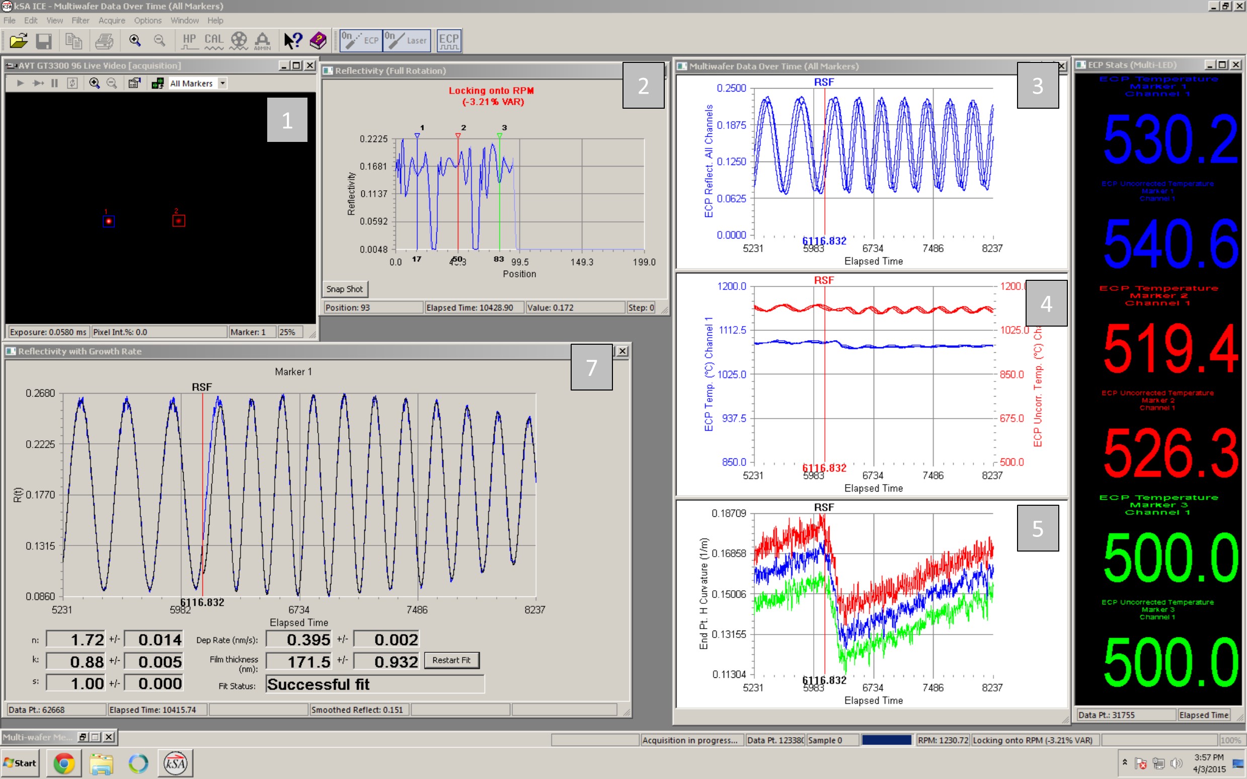
- Utilizes signal intensity changes in the wafer and carrier to visually trace and define wafer positions during rotation. The user is able to accurately place measurement “markers” at any position to enable real-time monitoring. Wide markers are available when averaging is desirable.
- Multi-wafer acquisition for full real-time integration and display of all pertinent acquisition parameters, at all marker positions (up to 20 markers).
- Capable of dynamically adjusting the laser and/or detector integration times to maintain the highest S/N upon surface reflectivity changes during film deposition.
- Complementary analysis software for post-deposition/acquisition analysis. Data storage in ASCII, Excel, or binary file formats facilitates alternative data analysis by user.
- Transports graphics directly to Windows clipboard or exports directly to .wmf, .bmp, .png, or .tif formats. Export data to .xls and .txt formats.
- Complete TCP/IP interface for custom, real-time data transfer and program control.
- Ability to write data in real-time to an SQL database.
- Complete analog and digital data I/O capability.
- User configurable window layout.
| 1 | -MOS: Live video image showing two reflected laser spots from the sample |
| 2 | -R: Reflectivity trace over a full rotation (Note the user placed markers at the centers of 3 wafers and the remaining 2 pockets were empty.) |
| 3 | -ECPR: ECP Reflectivity vs. time measured for each marker |
| 4 | -ECPR: ECP Temperature and ECP Uncorrected Temperature vs. time measured for each marker |
| 5 | -MOS: Curvature vs. time measured for each marker |
| 6 | -ECPR : Latest ECP Temperature (Corrected and Uncorrected) values measured for each marker position |
| 7 | -R: Reflectivity with Growth Rate Chart measured for Marker 1 |
kSA ICE software screen shot with multiple real-time multi-wafer measurements
Distributors
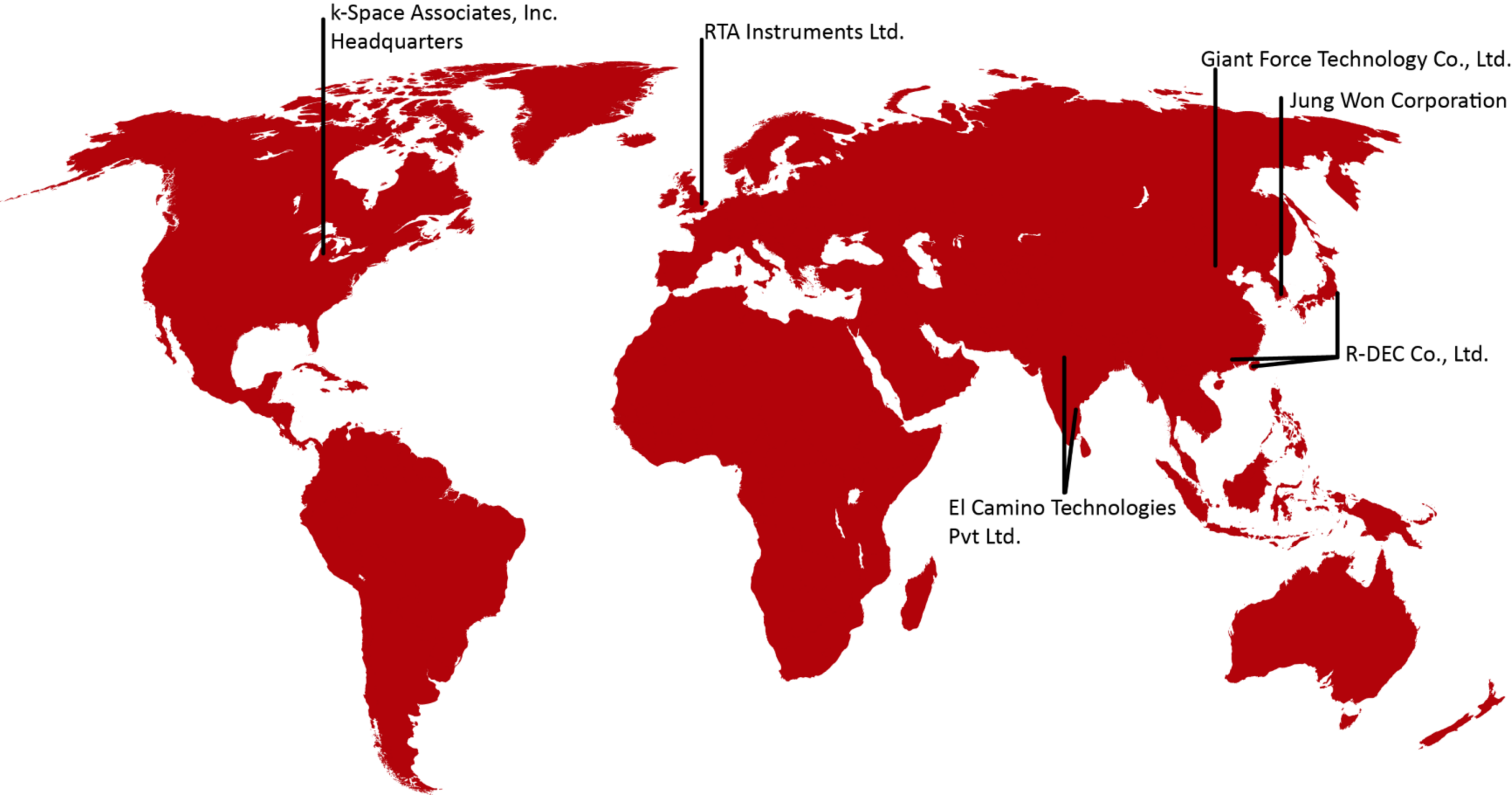
k-Space has an expansive network of distributors to best serve our worldwide customer base.
HEADQUARTERS
k-Space Associates, Inc.
Michigan, USA
www.k-space.com
[email protected]
DISTRIBUTION PARTNERS
RTA Instruments Ltd.
Europe
www.rta-instruments.com
[email protected]
El Camino Technologies Pvt Ltd.
India
www.elcamino.in
[email protected]
Giant Force Technology Co., Ltd.
China
www.giantforce.cn
[email protected]
Jung Won Corporation
South Korea
www.jwc.co.kr
[email protected]
R-DEC Co.,Ltd.
Japan
Hong Kong
Taiwan
www.rdec.co.jp
[email protected]

