Product Specifications : kSA ScanningPyro
Version: 1.0
- kSA ScanningPyro
- Functional Specifications
- System Specifications
- Data Acquisition Screen
- Data Analysis
- System Requirements
- Distributers
kSA ScanningPyro
Full Carrier
Temperature
Maps at the
Click of a Button!

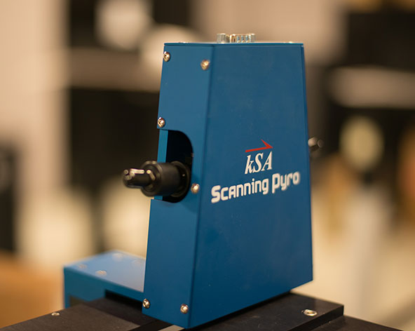
The kSA ScanningPyro metrology tool is designed to quickly, easily, and accurately generate full wafer carrier temperature maps on Veeco K465i and EPIK 700 production MOCVD reactors. The kSA ScanningPyro utilizes simultaneous temperature measurement from two sensor heads while scanning across the optical viewport, allowing for a full temperature map from platen center to platen edge in a single scan.
Quickly generate a full temperature map of your wafer carrier to determine temperature uniformity, adjust heater zones, and determine hot and cold spots. Easy-to-use k-Space software allows you to perform full carrier scans, or select any subset of a full scan, with selectable scanning resolution.
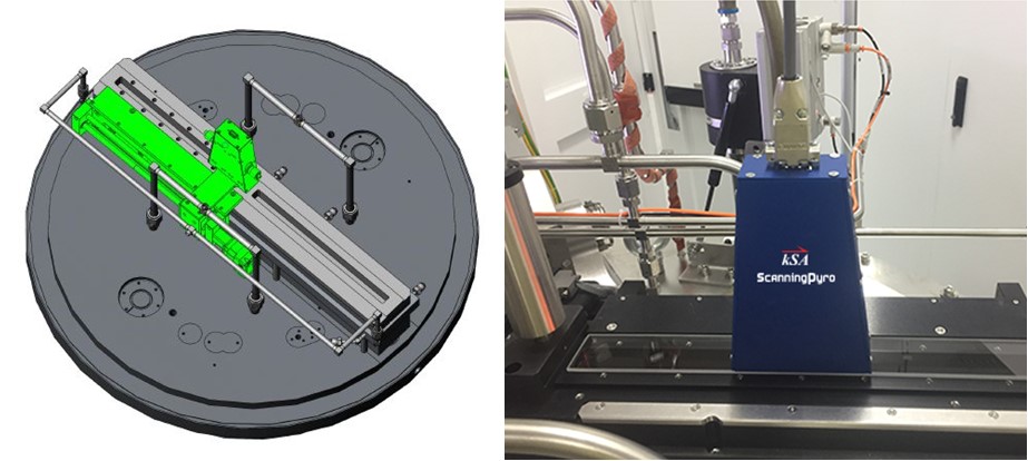
The kSA ScanningPyro optics head and scanning stage easily mounts above the right side viewport of the K465i or EPIK 700 reactor. The ScanningPyro pyrometers can either be calibrated to a known temperature set point, or calibrated to absolute temperature using the kSA SpectraTemp temperature measurement tool.
Functional Specifications
| Scanning Pyro Models and Compatible MOCVD reactors | SPYRO-465 for Veeco K465i and SPYRO-700 for Veeco EPIK 700 |
| Scan Range | Full carrier, or any subset specified by the user |
| Temperature Range | 530 - 1250°C (higher temperature range units available upon request, e.g. for AlN applications) |
| Temperature Resolution | 530-700°C: ±1.0°C 700-1250°C: ±0.3°C |
| Scan Resolution | User selectable, typical radial scan step size: 1mm, angular resolution: 0.3° or better |
| Scan Time | Depends on carrier rotation speed. For example, at a carrier speed of 600 rpm, for a full carrier scan on a K465i with 1mm radial step size, the full scan time is 93s. |
| Scan Schedule | User definable scan schedule to allow data acquisition at predetermined times for systematic correlation with growth recipes. |
| Temperature Analysis | Fully configurable analysis templates, as defined by the user. Automatic statistical analysis of min, max, average, and standard deviation of individual pockets, cumulative pockets, and web regions. Exclusion regions definable within the template. Full statistical analysis of user definable watch radii for direct comparison with Veeco Realtemp pyrometer measurements. Crosshair analysis with full rotation capability. |
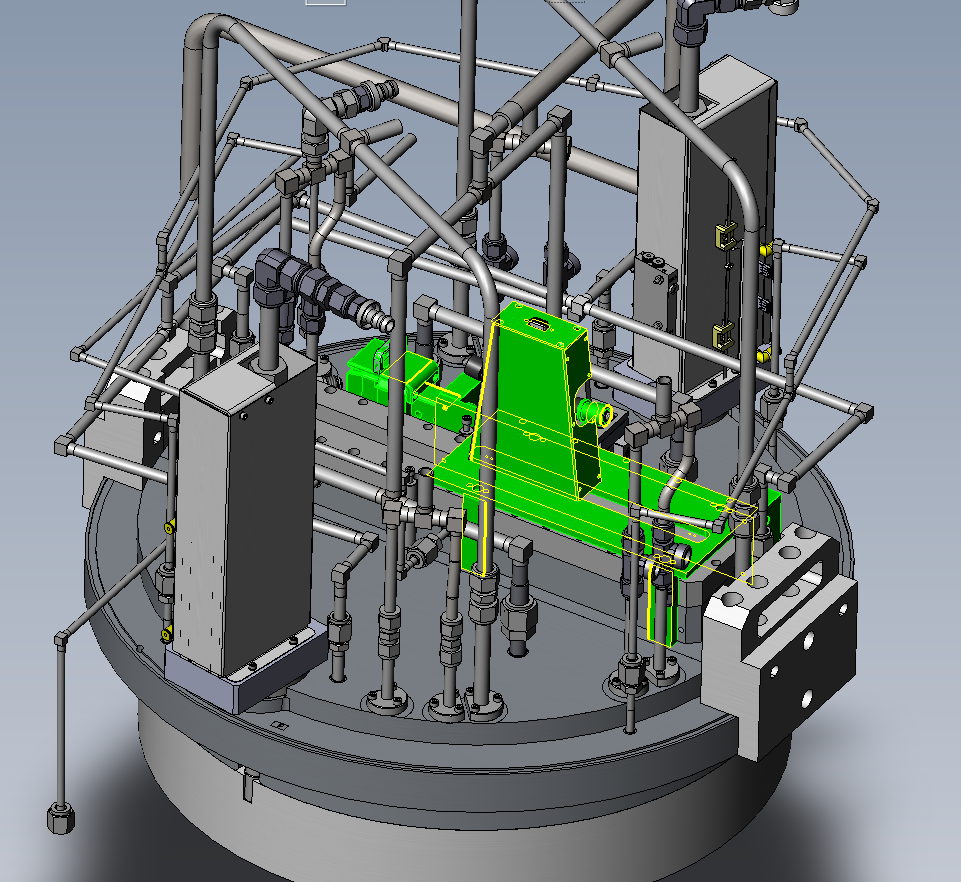
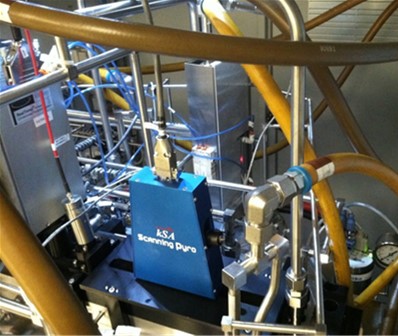
Mechanical drawing of the kSA SPYRO-465 footprint and a photograph of the kSA SPYRO-465 on a k465i reactor.
System Specifications
Controller
The kSA ScanningPyro is supplied with a fully configured, Windows 10 multi-core CPU, 3U rack mounted computer controller. User must have space and facilities for a computer controller and supplied 22” LCD monitor, keyboard and mouse within 3m of the front of the reactor. Please refer to the kSA Computer Product Specifications for the latest controller configuration. k-Space does not recommend customers substitute or update their own computer for the controller.
Electrical Specifications
System Power: 120VAC with 10A max or 230VAC with 5A max, 50/60Hz compatible. Power Connections: Requires a total of three power connections for the computer controller (2m power cable), the computer monitor (2m power cable), and the linear scanning stage (3m power cable).
Control Hardware and Cabling
The systems computer controller is connected to 1) system power (2m power cable), 2) optical head (9-pin D-sub to USB, 3m) , 3) rotational trigger (hardwired to trigger sensor and pigtail connection to controller with 9-pin D-sub for power and BNC for trigger signal input, 3m), 4) linear scanning stage motor (ribbon cable to USB, 3m), 5) monitor (2m power cable), 6) mouse, and 7) keyboard. All cables provided.
Installation and Training
A minimum of 1-2 days of on-site customer installation and training are required with system purchase.
Warranty
All kSA systems and integrated components are warranted against defective materials and workmanship for a period of ONE YEAR from the date of delivery to the original purchaser.
Mechanical drawing of the kSA SPYRO-700 footprint and a photograph of the kSA SPYRO-700 on an EPIK 700 reactor.
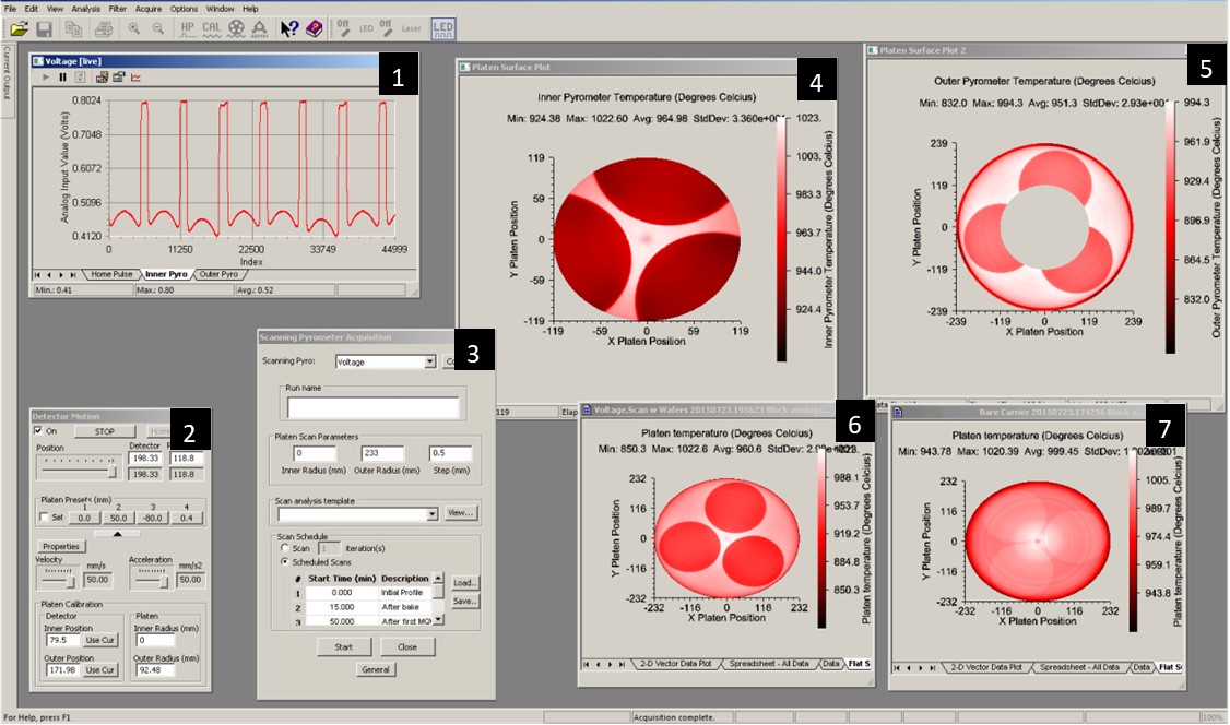
Data Acquisition Screen
| Window | Description |
|---|---|
| 1 | Live data acquired from inner and outer pyrometers. |
| 2 | Linear motion controller. The user can set up fully automated scans, or can move to any radius on the carrier and manually acquire data. |
| 3 | Scanning acquisition dialog. The scan parameters, including starting and stopping carrier radius and scan resolution, are user-selectable. The user may also define a time-based scan schedule. |
| 4 | The inner pyrometer acquires data on the inner half of the carrier. Notice the high resolution of the scanner: the wafer notches are clearly visible in this scan. |
| 5 | The outer pyrometer acquires data on the outer half of the carrier |
| 6 | The inner and outer pyrometer data are combined to provide a complete carrier map in a single scan. A full scan on the K465i carrier takes 93s with a 1mm step size at 600 RPM. |
| 7 | Full scan of an empty carrier (no wafers). |
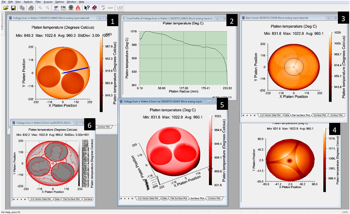
Data Analysis
| Window | Description |
|---|---|
| 1 | Full platen map with line profile selection tool (line plot shown in window 2). User can place the line profile at any position, length, and line width. |
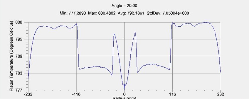
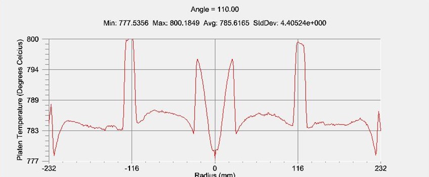
| 2 | Temperature line profile as a function of platen radius. Data plot of line profile selection tool is shown in window 1. |
| 3 | Full platen map of empty carrier (no wafers). The user defined circle selects a new, zoomed in surface plot; see window 4. |
| 4 | Zoom in of central area of full platen map shown in window 3. This data shows a hot zone at the inner edges of the wafer pockets, and towards the center of the carrier. The spindle keeps the carrier cooler at the very center. |
| 5 | 3D surface plot of full carrier map. |
| 6 | Contour plot of full carrier map. |
Data Analysis Features
Line Scan Capability:
User-defined lines on carrier maps generate line profiles and crosshair profiles for further analysis. The example below shows crosshair line profiles. In this case, there are wafers in the pockets. The wafer temperature appears lower than that of the wafer carrier due partially to the difference in the emissivity of the wafers and the carrier.
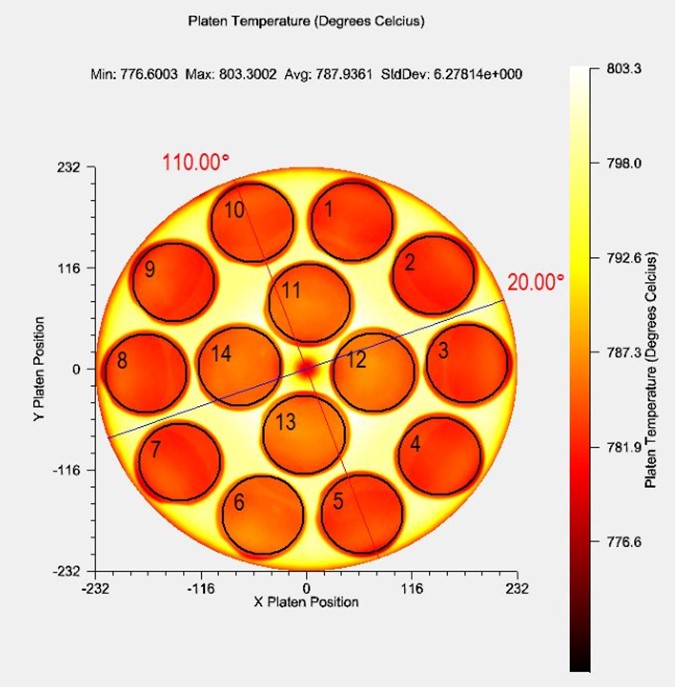
Web and Pocket Analysis:
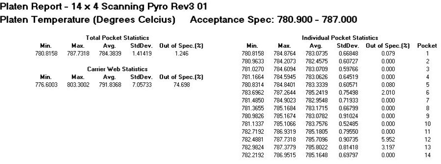
A user-defined wafer template may be used to automatically generate a Platen/Carrier Report at the completion of the scan. A 14×4” wafer template is shown in the adjacent carrier map, with each wafer/pocket labeled 1-14. This analysis tool determines the wafer/pocket and web temperature statistics over the entre web and pocket regions and for the individual pocket regions. The user may also define exclusion regions for this analysis as well as specify acceptance specification criteria for the measured parameter. This can be used to track specific wafer/pocket temperatures for each growth.
System Requirements
The kSA ScanningPyro is a dual-pyrometer based temperature mapping tool designed for production MOCVD reactors with slit-style viewports. The system requirements described here are specifically for the Veeco K465i MOCVD reactor.
Controller
The kSA ScanningPyro is supplied with a fully configured, Windows™ 10, multi-core CPU, 4U rack mounted computer controller. User must have space and facilities for a computer controller and supplied 22” LCD monitor, keyboard and mouse within 3m of the front of the reactor.
Electrical Specifications
System Power: 120VAC with 10A max or 230VAC with 5A max, 50/60Hz compatible.
Power Connections: Requires power connections for 1) computer controller (2m power cable), 2) computer monitor (2m power cable), and 3) Linear Scanning Stage (3m power cable). All power connections configured for China CPCS-CCC (Type I) for shipments to China.
Control Hardware and Cabling
Computer controller is connected to 1) System Power (2m power cable), 2) Optical Head (9-pin D-sub to USB, 3m) , 3) Rotational Trigger (hardwired to trigger sensor and pigtail connection to controller with 9-pin D-sub for power and BNC for trigger signal input, 3m), 4) Linear Scanning Stage Motor (ribbon cable to USB, 3m), 5) monitor (2m power cable), 6) mouse, and 7) keyboard. All cables provided.
Mechanical Mounting
Optical Head/Linear Scanning Stage Mounting: When facing the FRONT of the K465i reactor, the right side of the viewport must be clear of any metrology tools, i.e. all RT (Veeco RealTemp) and DRT (Deflectometer and RealTemp) metrology optics must be removed from the right side viewport. The photograph and drawings show the position of the kSA ScanningPyro on the right side viewport of the K465i reactor. The unit is connected to the reactor top via four stand offs; mounting hardware and bolts are provided. The linear scanning stage is controlled by the computer and software via a ribbon/USB cable and has independent power connection. Attached to the optical head and supported by the mounting hardware, the motor controls the scanning of the optical head across the slit. The optical head has one connection to the control computer.
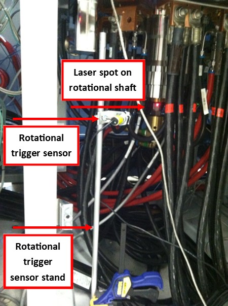
Rotational Trigger Mounting: An optical trigger sensor is placed on the underside of the reactor cart, as shown in the photograph. The kSA ScanningPyro is supplied with a sensor, sensor stand and reflective tape. The sensor is mounted to a rod with platform which stands on the floor. A small piece of reflective tape is placed on the rotation shaft for rotational pulse positioning. The trigger sensor has a pig-tailed cable for two connections to the control computer (cable length 3m).
Optional Accessories: A pocketless carrier can be supplied with the system at additional cost. The pocketless carrier is
very useful for precise measurement of temperature uniformity of the underlying heater elements.
Distributers

k-Space has an expansive network of distributors to best serve our worldwide customer base.
HEADQUARTERS
k-Space Associates, Inc.
Michigan, USA
www.k-space.com
requestinfo@k-space.com
DISTRIBUTION PARTNERS
RTA Instruments Ltd.
Europe
www.rta-instruments.com
info@rta-instruments.com
El Camino Technologies Pvt Ltd.
India
www.elcamino.in
chetnamohan@gmail.com
Giant Force Technology Co., Ltd.
China
www.giantforce.cn
giantforce@gmail.com
Jung Won Corporation
South Korea
www.jwc.co.kr
salesinfo@jwc.co.kr
R-DEC Co.,Ltd.
Japan
Hong Kong
Taiwan
www.rdec.co.jp
info@rdec.co.jp