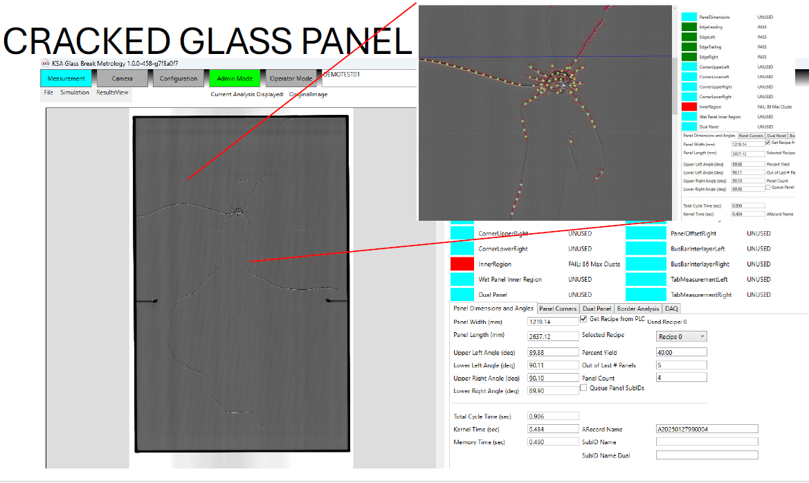
Real-time visual and data analysis of glass breakage and defects (scratches, digs, cracks, chips, pinholes, etc.) to quickly quarantine or scrap inline defective product as it moves along the line.
Description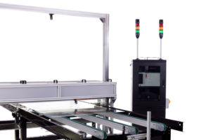
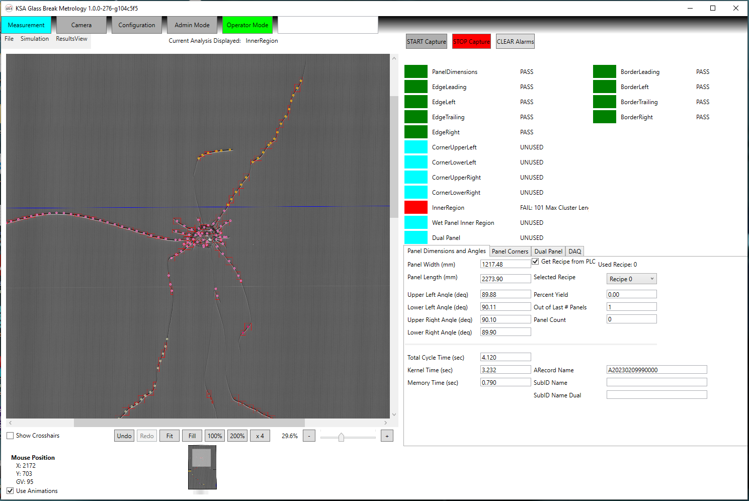
The kSA Glass Breakage & Defect Detection tool is a vision-based metrology system that determines Go/No-Go (Pass/Fail) conditions for every glass lite and panel it inspects inline during processing. The tool accomplishes this by comparing coated or uncoated glass lites and panels against user-defined parameters and tolerances in a master specification reference to identify defects such as cracks, chips, scratches, digs, and pinholes.
Details
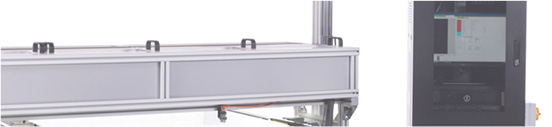
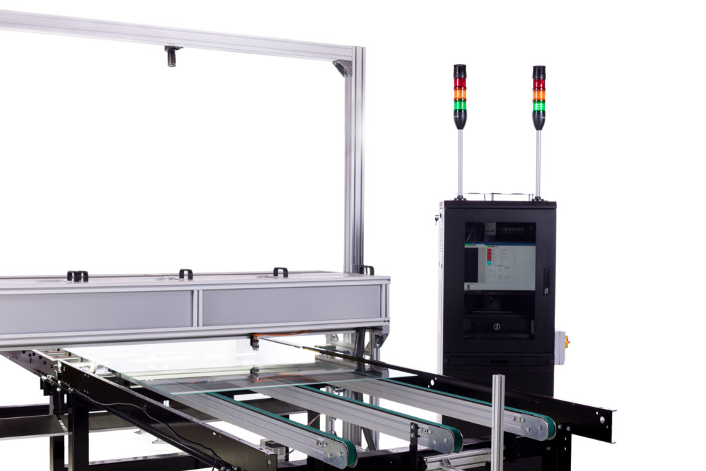
- The custom frame enclosure houses a linescan camera, LED lights, and photoeyes.
- The camera vision system captures images of the panels as they pass by the instrument on a conveyor.
- LED lights illuminate the panels to help distinguish between defects and minor irregularities.
- Photoeyes detect the leading and trailing edges of the panels to trigger the system to start and stop data collection.
- High-resolution encoders trigger spatially-resolved linescans as the panel moves under the LED lighting, generating a high-resolution image of the panel for detailed image processing and defect detection.
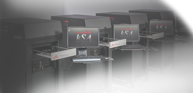
- The CPU provides image processing and data storage capabilities.
Benefits
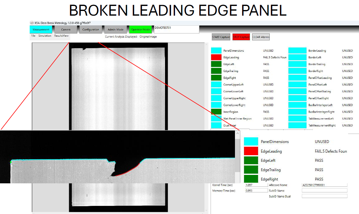
- Real-time visual and data analysis of glass breakage and defects (scratches, digs, cracks, chips, pinholes, etc.) to quickly quarantine or scrap inline defective product as it moves along the line.
- Early detection of defects and anomalies results in reduced down time and scrap costs.
- Documented compliance with applicable glass visual and safety standards (ASTM, ANSI) ensures consistency across all glass lites and panels.
- Customizable software enables users to configure the settings to fit their specific needs.
- In-process QC validation ensures that all lites and panels conform to the custom master standard.
- Factory integration capabilities enable facilities to incorporate the tool into existing systems (factory alarms, PLC, email alerts, etc.).
Capabilities

- Detects defects as small as 200 microns.
- Provides high-resolution line-scan camera system options (up to 1,000 samples/second) to meet desired conveyance line speed and image resolution
- Captures high-resolution glass panel images and stores data for the user-selected lites and panels (failed, random, all, etc.)
- Handles both clear/transparent glass and opaque glass using high-intensity (>14K lux at 500 mm working distance) LED light bar modules with safety shielding
- Includes built-in Calibration/Gage R&R testing
- Starts and stops data acquisition based on triggers from the in-line photo eye detectors
- Allows skew of +/- 5° through the scanning process
- Supports conveyor line speeds ranging from 1 to 36 m/min (balanced against resolution/accuracy requirements)
- Scans clear or coated glass of thicknesses ranging from 2 to12 mm
- Supports tempered or heat-treated glass with distortion of +/- 15 mm
- Measures in situ panels up to 1.2 x 2 m (single camera system) with +/-0.5 mm accuracy
- Supports multiple-lite loads
- Applies a customized reference standard based on pass/fail limits on user-specified parameters and tolerances
- Captures, analyzes, and stores data using proprietary k-Space software
All of this is accomplished through the glass breakage detector, which includes the frame with detectors and standalone electronics cabinet with rackmount CPU, monitor, keyboard, and mouse.
Software 
- Fully customizable user interface and data acquisition to meet user needs
- Capable of acquiring data from a live source or a saved data file
- Capable of filtering or smoothing data using a variety of methods and parameters
- Able to write to SQL databases and files for off-line analysis with statistical software tools, such as JMP from SAS

Technology

- The custom frame enclosure houses photo eyes, LED lights, and a single line-scan camera.
- Photo eyes detect the leading and trailing edges of the panels and trigger the system to start and stop data collection.
- LED lights illuminate the glass panels from underneath the conveyance system to help distinguish between defects and minor irregularities.
- The camera vision system captures linescan images to identify glass edge dimensions and then captures full area images of the glass lites and panels as they pass by the instrument on a conveyor.
- High-resolution encoders trigger spatially resolved line scans as the panel moves over the LED lighting system, generating a high-resolution image of the panel for detailed image processing and defect detection.
- The CPU provides image processing, data analysis, and data storage capabilities.
Case Studies
Product Information
Videos