Product Specifications : kSA MOS
Control Your Stress! In Situ Curvature and Thin Film Stress Monitoring
Version: 1.0
Intro
 Click to Enlarge
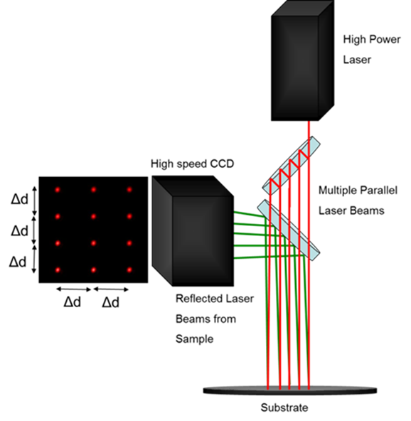
kSA Multi-beam Optical Sensor (kSA MOS) is an extremely sensitive laser based system for in situ, real-time monitoring of thin film stress. The stress measurement is performed by monitoring the substrate curvature with an array of parallel laser beams and a camera. Since the technique is optically based, it is compatible with most thin-film deposition processes, including CVD/MOCVD, PVD, ALD, sputtering, electrochemical depositions, and MBE provided that optical access to the substrate is available. The system is ideally suited for real-time feedback to process control systems in the production or research environment.
| Measures |
|---|
| Curvature |
| Thin film stress-thickness |
| Thin film stress |
| Reflectivity |
| Growth rate and optical constants (n,k) of semi-transparent films in real-time during the deposition process (Optional) |
| Applications |
|---|
| Real-time data during film deposition process |
| Real-time data during thermal processing |
| Real-time data during electro-chemical deposition |
Data used for analysis of:
|
kSA MOS Overview
The kSA MOS patented technology uses a single laser to generate a two dimensional laser array of spots which are reflected off the sample surface and into a high resolution camera. Changes in the laser array spot spacing are used to determine the changes in sample curvature. Because the system simultaneously measures the spacing between laser spots in two orthogonal directions, the kSA MOS provides two dimensional curvature data which is not possible with curvature tools that use point/line scan with mechanical rastering. Simultaneous detection of the laser array also makes the measurement inherently less sensitive to sample vibration compared with scanning systems. Since all the laser spots move together at the same frequency, movement or tilt is not detected as a change of curvature and thus leads to increased curvature resolution capability.
The kSA MOS also features the patented and automated servo-motor control of an optical flat mirror to provide fully automated tracking capability during data acquisition. This feature is of particular use in monitoring curvature/stress during high temperature annealing where thermal expansion may cause angular displacement of the sample and thus the reflected laser array.
Moreover, during films deposition, the surface and overall sample reflectivity may change due to material properties and/or surface morphology. k-Space has developed and patented a software-controlled method for dynamically adjusting the detector exposure time to maintain the highest S/N during these changes.
kSA MOS Standard Package
| Model | Description |
|---|---|
| kSA MOS MOS | Complete Curvature and Film Stress measurement system includes:
|
| Options | Description |
|---|---|
| 405 nm Laser and Optics M-HRD/U |
|
| Large Format Camera M-HRD/U |
|
| Growth Rate Monitor Option MOS-GM |
|
| Analysis Only Software M-AOS |
|
| Laser Based Rotational Trigger Generator kSA-TRG |
|
| Encoder Based Rotation Monitor and Trigger Generator kSA-RMT |
|
kSA MOS Specifications
Lasers
The kSA MOS system utilizes fiber coupled, Peltier cooled laser diode packages with integrated current controller and temperature controller for generating the laser array. A different laser wavelength and associated optics may be required /desirable for some applications. Note: All high-power beams are confined within the MOS housing even when the cover is removed for alignment. The cover is not interlocked, but may be upon request. Direct access to the main beam is necessary during alignment.
| 660 nm (MOS Standard) | 405 nm (M-405/U) | |
|---|---|---|
| Operation Mode | Constant current | Constant current |
| Spot Size | ~ 0.8mm spot diameter, typical array is 6x4 mm ( 4x3 array) | ~ 0.8mm spot diameter, typical array is 6x4 mm ( 4x3 array) |
| Power | >70mW ( <10µW exits the optical enclosure) | > 50mW ( <10µW exits the optical enclosure) |
| Stability | ≤ 0.2% | ≤ 0.2% |
| Lifetime | 10,000 hours (mean time before failure), 1 year warranty | 10,000 hours (mean time before failure), 1 year warranty |
Detectors
The kSA MOS system utilizes a camera for imaging the laser array. The larger format detector offers a factor two increase in convex curvature range and greater sample wobble tolerance and may be required for some applications.
| Standard Detector | Large Format Detector Upgrade (M-HRD/U) | |
|---|---|---|
| Model | k1400-12 | k3300-14 |
| Curvature Resolution | Up to 2x10⁻⁵m-1 (1-sigma std. dev.) | Up to 2x10⁻⁵m-1 (1-sigma std. dev.) |
| Camera Format | 2/3 type, Sony ICX285 Progressive Scan | 4/3 type, KAI-08050 Progressive Scan |
| Resolution | 1360 x 1024 pixels (1.4MP) | 3296 x 2472 (8MP) |
| Pixel Size | 6.45 μm | 5.5 μm |
| Sensing Area | 8.8 mm x 6.6 mm | 18.13 mm x 13.6 mm |
| Spectral Range | 400-1000 nm | 350-1100 nm |
| Bit Depth | 12-bit | 14-bit |
| Dynamic Range | 58 dB | 62 dB |
| Frame Rate | 30 fps full resolution | 14.7 fps full resolution |
| Exposure Time | Variable from 10 μs to 77.3 s | Variable from 10 μs to 26.8 s |
| Output Format | GigE | GigE |
| Lens Mount | C-type | C-type |
| Power | 12V DC (internal from computer) or external 120/240V 210 mA current consumption | 12V DC (internal from computer) or external 120/240V 210 mA current consumption |
| Camera Dimensions | 59(W) x 46(H) x 33(D) mm | 121(W) x 59.7(H) x 59.7(D) mm |
Analog/Digital I/O Communications
Optional Analog/Digital I/O communication hardware is software configurable for use as real-time feedback to deposition equipment. Please contact a k-Space representative with your A/D communications needs so that the appropriate hardware can be quoted.
Controller
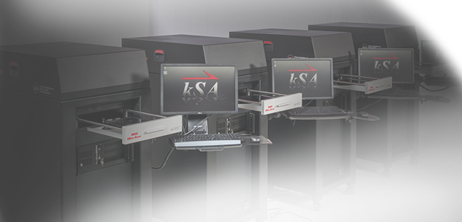
The kSA MOS system is supplied with a fully configured, Windows 10, multi-core CPU computer system with a 22” LCD Monitor. Please refer to the kSA Computer Product Specifications for the latest computer configuration. k-Space does not recommend or encourage customers to substitute or update their own computer for the controller. The MOS system uses several data acquisition boards that require specific bus slots and additional I/O slots on the back plane of the computer chassis.
Measurement Triggering
The MOS controller supports rotational triggering signal via a BNC connection which accepts signal with a 2 V to 30 V rising/falling edge pulse and a pulse with greater than 500 μs.
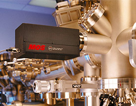
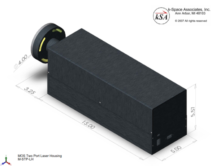
Optical Enclosures
The kSA MOS system is supplied with either a single port or dual port optical enclosure configuration. To confirm the best configuration for your chamber or application, please contact k-Space for more information.
- The single port enclosure requires normal incidence mounting with respect to the sample surface either by direct line of sight or through the use of fold mirror optics (sold separately.) If the system will be looking through a viewport, the viewport material should be angled with respect to the MOS enclosure. Angled viewports for 1.33” CF, 2.75” CF and 4.5” CF flanges are available from k-Space.
- The two port enclosures must be mounted at specular angles with respect to the surface normal of the sample. In this case an angled viewport is not required.
- Attachment to chamber ports requires the use of a retaining ring that is mounted under the viewport bolts and thus must be installed while the system is not under vacuum.
| Standard MOS Single Port Enclosure | Standard MOS Two Port Enclosure |
|---|---|
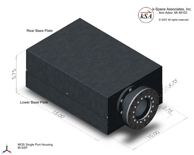 |  |
 |
Installation and Training
A minimum of 1-2 days of on-site customer installation are required with system purchase.
Customer Facility Requirements
System Power: 110-240 V, at 220 V system draws ~3-4 A.
Warranty
All kSA systems and integrated components are warranted against defective materials and workmanship for a period of ONE YEAR from the date of delivery to the original purchaser.
kSA MOS Integrated Software
Software Capabilities
- Complete data acquisition and analysis control.
- Automatic laser spot detection.
- Automatic camera exposure control to ensure no saturation of detector as surface reflectivity changes.
- Real-time plotting of intensity, reflectivity, differential spot spacing, stress-thickness product, strain, and radius of curvature.
- Data acquisition modes:
1) Focus mode: for facilitating laser alignment and optics focusing by simultaneously monitoring the image and a line profile of the laser spot array.
2) Curvature/Strain Mode: An arbitrary number of laser spots, user configured, are tracked simultaneously; yielding time-resolved radius of curvature measurements, mean differential spot spacing, stress, reflectivity, and intensity. The mean differential spot spacing is used to calculate time resolved stress or stress thickness product using material parameters.
- For time-resolved acquisition modes, a delay time between image acquisitions, may be selected.
- External triggering can be used to time data acquisition with external events or substrate rotation.
- Analysis Capabilities:
1) Line profile for accurate determination of beam profiles.
2) Radius of curvature and strain analysis. User input of physical geometry and substrate parameters yields calculation of radius of curvature, stress-thickness product, or relative stress as a function of time, temperature, or other user configurable input. Alternatively, simple centroid position and spot separation distance may be plotted.
- Data storage in ASCII, Excel or binary file formats facilitate alternative data analysis by user.
- User-friendly Windows 10-standard environment with extensive error checking and file handling. Data storage in ASCII, Excel or binary file formats facilitate alternative data analysis by user. Direct printing of images or graphics using currently loaded Windows printer drivers. Cut-and-paste directly to clipboard, or into other applications such as MS Word or PowerPoint.
- High-quality 2D and 3D graphics for data display. Numerous image and graphics editing capabilities, including false coloring using pre-loaded or user-defined color palettes, and label editing. Transport of graphics directly to Windows clipboard or exported to Windows Metafile, Tiff or Bitmap format.
- Complete TCP/IP interface for custom, real-time data transfer and program control. Ability to write to an SQL database. Analog and Digital I/O capability with optional hardware (quoted separately).
Optional Software
kSA MOS Analysis Only Software Sentinel Key (M-AOS)
M-AOS option is an analysis-only software sentinel key that allows complete kSA MOS functionality, with the exception of data acquisition. It is designed for users who want to perform post acquisition, display, processing and analysis away from the laboratory.
Growth Rate Monitor Option for kSA MOS Software (MOS-GM)
As an add-on to the standard MOS software, the MOS-GM software option offers:
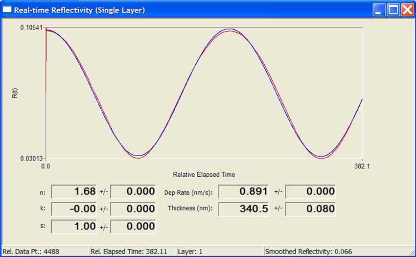
- Reflected intensity oscillation data recorded during growth can provide accurate growth rate and optical constant determination for semi-transparent films.
- Real-time update of current n, k, deposition rate, and standard deviation of these values.
- Ability to generate a thin-film deposition recipe, so multiple layers can be properly fit in real-time. Each layer in the recipe will have a user-estimated n, k, and G value. Each layer can be triggered via a time-based kSA MOS software recipe or an external trigger signal (with the purchase of additional A/D communications options or via the integrated TCP/IP protocol.)
- Optional ability to output growth rate, thickness, n, and k to analog output channels for input into process control system.
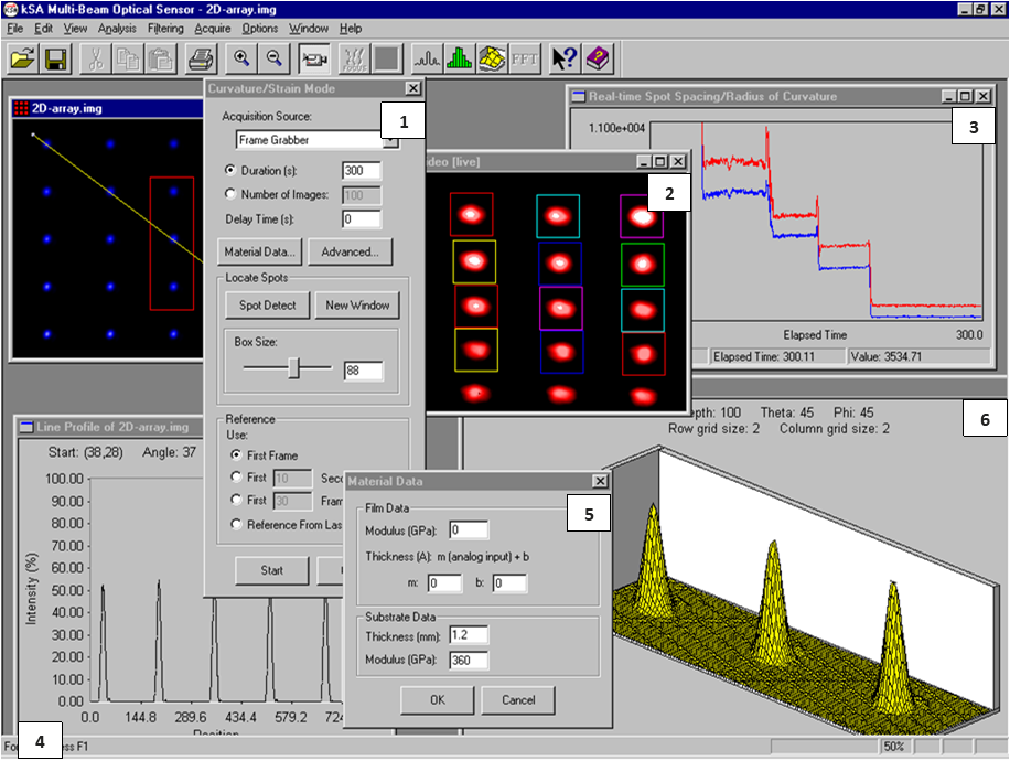
| 1 | kSA MOS Curvature/Strain Mode acquisition dialogue window. |
| 2 | Live video image showing twelve reflected laser spots from the sample. |
| 3 | Real-time radius of curvature data measured in the horizontal and vertical direction of the laser array. |
| 4 | Line profile of laser spots. |
| 5 | Material Data dialogue, values used for determining film stress. |
| 6 | 3-D plot of laser spot used for ensuring proper optical set up and beam alignment. |
kSA MOS software screen shot of multiple real-time measurements
Distributors

k-Space has an expansive network of distributors to best serve our worldwide customer base.
HEADQUARTERS
k-Space Associates, Inc.
Michigan, USA
www.k-space.com
[email protected]
DISTRIBUTION PARTNERS
RTA Instruments Ltd.
Europe
www.rta-instruments.com
[email protected]
El Camino Technologies Pvt Ltd.
India
www.elcamino.in
[email protected]
Giant Force Technology Co., Ltd.
China
www.giantforce.cn
[email protected]
Jung Won Corporation
South Korea
www.jwc.co.kr
[email protected]
R-DEC Co.,Ltd.
Japan
Hong Kong
Taiwan
www.rdec.co.jp
[email protected]